Smart controlled daisy-chain RGB LEDs
Recommendations: 16
About the Project
A while back I made some sci-fi terrain and embedded loads of tiny 0805 sized LEDs in the walls and around doors. It was pretty cool but took a *lot* of effort to control them all independently. Instead of single-colour LEDs (wired in parallel) I thought I'd try a "generic lighting system" using WS2812B (neopixels) which allow the user to cascade as many LEDs into a chain as they like. This will be a slow-burn project, built over a number of months as time and access to components allow (buying stuff in China may be cheap but it can take months to arrive!)
Related Genre: Game Aid
This Project is Completed
Individually controllable RGB LEDs FTW
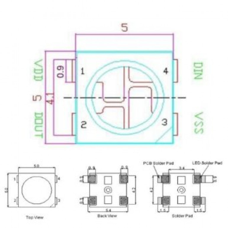
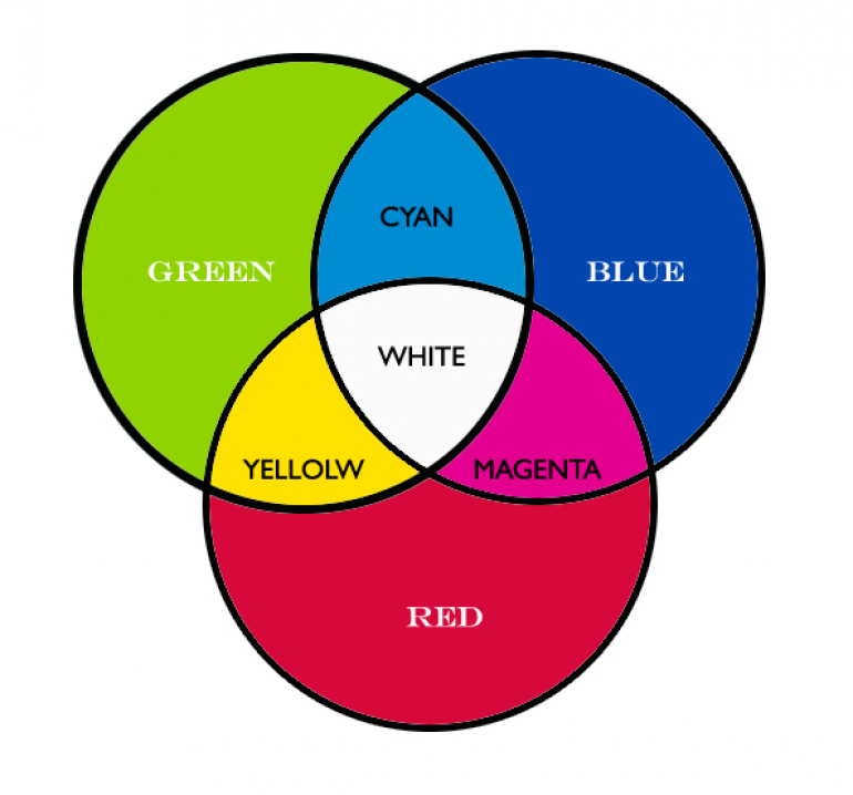
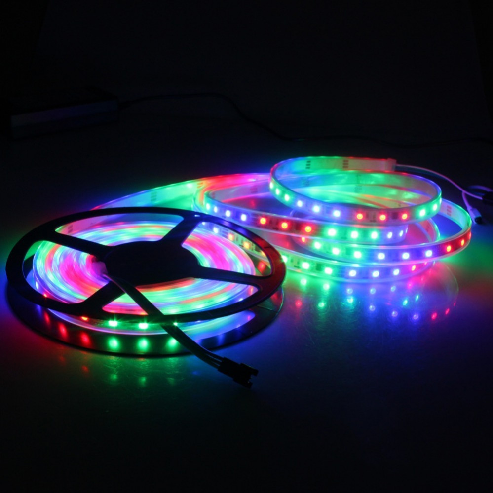
WS2812 RGB LEDs are brilliant, easy-to-control individual compound LEDs. Each one has red, green and blue channels and you can blend the intensity of these three colours to create pretty much any colour you like.
For example, if you were to set the red and green channels to full strength, with zero blue, you’d create an orangey-yellow colour. Half intensity red and full blue would give a subtle indigo shade and so on. All three at full brightness create white light.
One of the best things about the WS2812B is that it can be “daisy chained” – meaning if you want to control more than one LED, you can simply keep adding to the end of the chain.
Another brilliant thing about them is that they are individually addressable; so you can make the first in the chain a red colour, the next blue, the next yellow, the next white, the next two turned off completely, the next purple and so on.
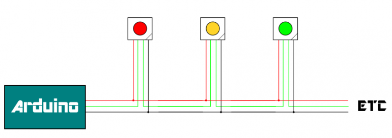
They also use a single data wire to connect them together – so just three wires and you can have as many LEDs as you like, all chained together, and all individually controllable.
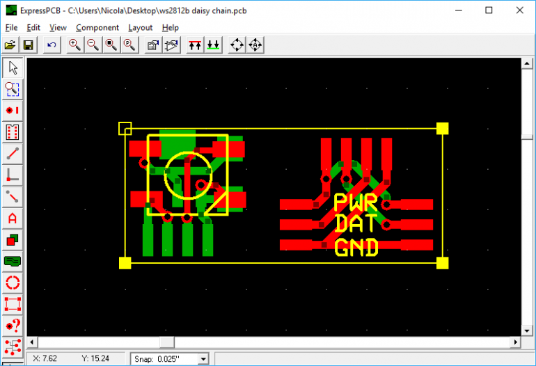
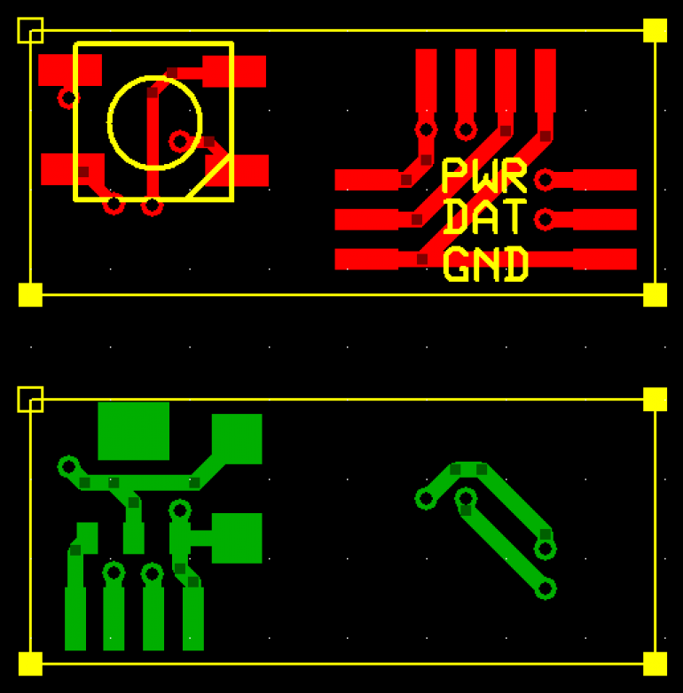
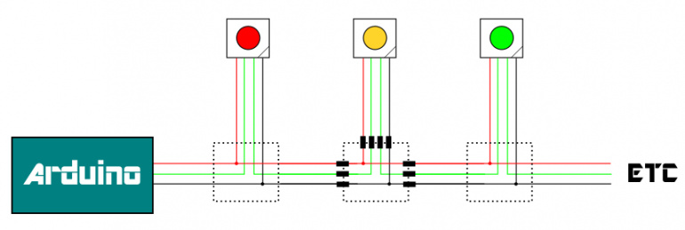
This PCB design is for two parts – to allow for maximum flexibility, then plan is to have a “ring main” – carrying the power, data and ground lines – and then from this, create a “spur” with each individual “pixel” or LED.
The PCB is double-sided and will have to be manufactured in a factory (in China) as creating something so tiny and precise and prone to error is bound to test even my patience for soldering tiny components to even smaller copper traces!
Arduino neopixels
Arduinos are great little microcontrollers with a huge community to support people getting into hobby electronics. This abundence of people prepared to “have a go” is both the greatest strength of the community, but also one of it’s weaknesses.
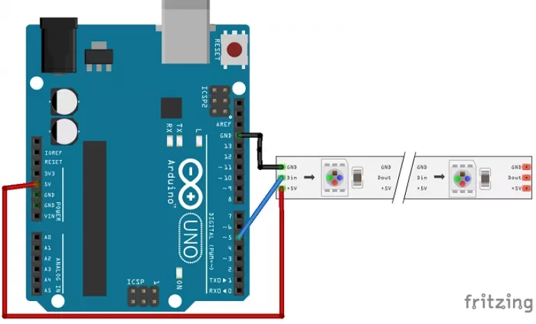
Here’s an example of how to make a string of LEDs light up, using an Arduino. Simply follow the diagram, copy and paste some code and off you go – working multicoloured LEDs!
The problem comes when you “outgrow” the examples; many people never need or want to light up more than a dozen or so LEDs – few progress much beyond the example code provided. So what happens when you attach, say, 30 LEDs, and each is connected via really tiny, super-fine, thin wires, rather than joined together in a convenient roll, straight from an eBay electronics store?
Long, tiny, thin wires effectively act like resistors in our circuit. They allow current to flow, but over any kind of distance (even relatively small distances, if the wire is thin enough) we encounter a phenomenon called “voltage drop”.
If you’re into things like that, you can measure the resistance of the wire and use Ohm’s Law and all that to work out precisely how much voltage you’re losing. For the rest of us muggles, we can just think of it like a leaky pipe. A few short runs of leaky pipe, and everything is ok. But if we have a great length, by the time we get to the end of the pipe, little more than a dribble falls out of the end!
Our LEDs require a good, stable 3.5V minimum to work consistently (5V is preferred). Less than this and they behave erratically (and you lose the ability to set each one individually). So we’re going to use a “voltage regulator” on each individual LED and provide much more than 5V on the supply lines. The idea being that if, say, we use a 9V supply and, over the course of 30 individual LEDs, the voltage drop in the wires means only 7V is getting to the last module in the chain, we’ll still have enough supply voltage to “step down” to 5V.
By putting a regulator on every module also means that LEDs closer to the voltage supply don’t appear brighter than those further down the line (as some LEDs will be being fed with a higher voltage).
So we need to create two PCBs per LED.
One for the LED to sit on, with the voltage regulator to drop the incoming voltage (anywhere from 9v to 7v depending on its distance from the power source) and another to connect the individual LED to the “ring main”.
The actual PCB designs are pretty simple.
I didn’t even bother building a prototype – I knocked up a few drawings and sent off for ten of each PCB to be made as cheaply as possible; it will probably take a couple of weeks for them to arrive, so I’ll update the project as and when progress is made……..
Inventing a language of your own
A bit like when you LARPers head of to UKGE and camp out with the Orcs by the lake, there’s nothing like creating your own language to make you feel like you’ve truly arrived in the Nerd World.
Luckily for us, we need only a really simple language to “talk to” our LEDs.
We already know that they’re going to be “daisy-chained” so the easiest way to control each one individually is to number them, then send a message to just one specific LED.
Sadly our LEDs are pretty dumb things. Their vocabulary consists of “how much red, how much green and how much blue?” That’s all they understand. They have no idea what “orange” is, or what shade “magenta” should be.
So something as simple as “oi, you, number six, give it full beans on the blue and green channels and nothing on the red” should suffice for our language.
While, in theory, we can have an “unlimited” number of LEDs in a chain (or, at least, until the voltage drop between the power source and the last one is so great as to provide less than around 6.5V into our voltage regulator) in practice, it’d make sense to put an upper limit on the number of LEDs on our chain, just for the sake of keeping our language nice and simple.
I reckon 256 should be plenty LEDs for anyone. It’s also a really nice number to use in 8-bit computing. We can represent and number between 0-255 using just two characters. For the uber-nerdy types, we’re in danger of stumbling into hexadecimal territory here. For the rest of us, we just need to know that, in our simple language, we can use two characters to signify any number up to 255.
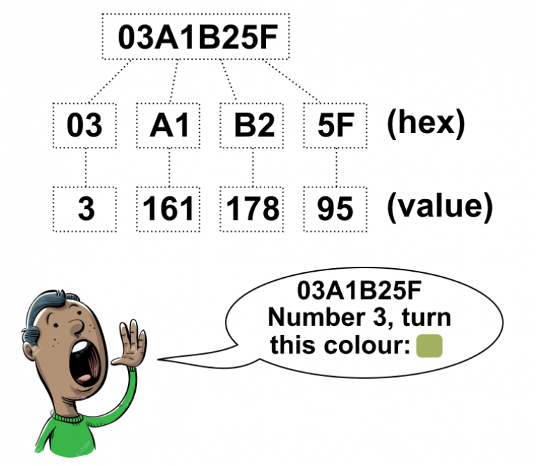
So our language will be to blurt out a succession of four numbers.
- The first is the number of the LED we want to control
- The second is the amount of red (0 = off, 255 = full power)
- The third is the amount of green light we want
- The fourth is the amount of blue
Using hexadecimal also provides some basic error checking for our system. Because we know that every message “packet” will contain four numbers – never three, that’s too few, and never five, that’s too many, and because we can represent each number with exactly two characters, our first sanity check is that a valid message must always have eight characters (4 x 2 = 8)
So when we receive a message, we first check that it is exactly eight characters long. If it is, we then chop it up into four parts, turn each part into a number and then assign the corresponding amounts of red, blue and green to the appropriate LED.
Simples 😉
It's Sunday, there's a few hours left of the weekend....
…. so it’s time to make progress with this little project.
At the minute, we’re doing little more than making LEDs turn on and off. Big deal? Well, yes and no. Because we’re not using mechanical switches; we’re using a chain of LEDs and a sending coding computer messages to turn them on and off.
(note that the colours in real life are far more concentrated and vibrant and don’t create the nasty bloom effect – that’s just my camera trying to cope with a tiny point of bright LED light and making a mess of it!)
Not just switching them on and off of course. Also changing the colours. Individually.
We’re able to say “LED number two, you should be green” and it just does it. Or we can say “LED number one, turn off” and it goes out (actually, we’re saying “set your red, green and blue intensities to zero” but the result is the same).
What particularly nice about this set up, is that it’s completely hot-pluggable. You can start off with one LED, then add more later and instantly control them – no need to update firmware or make changes to anything else; simply plug in another LED and off you go!
Which, admittedly, isn’t particularly impressive on its own.
Where things get really interesting is when we stick an app on a smart device and let users control their terrain lighting from their phone/tablet. I just need to work out if there are enough hours left this weekend to get one quickly coded up for a demo……
A quick-and-dirty controller app
I’ve only had a couple of hours at this, but – like many “completed” projects – it’s functional enough to call done for now! Here’s a simple controller app that lets the user select any of the LEDs in a string (of WS2812B daisy-chained together) and both set the colour or turn it on/off with a simple toggle switch
Obviously the immediate purpose is to be able to embed these little RGB LEDs throughout some terrain and to be able to control them remotely.
Possible uses include atmospheric lighting (increasing/decreasing the lighting in a dungeon, as players progress towards a goal, for example) door lock indicators (red could indicate locked and once the player has opened the door, the LED can be set to green).
You could even use it with vehicles for laser fire or explosions!
(maybe an update to the firmware is in order, to trigger pre-programmed animations, such as flickering lights, fading sequences and so on).
Anyway, there we go – a string of fully controllable, full-colour RGB LEDs that you can change via a smartphone/tablet.
The intensity of the colours and the pin-sharp focus of the LED lenses doesn’t really come across in the video (my camera is obviously trying to automatically adjust white balance and lighting levels for the best overall image) – in real life, the LEDs look a lot more impressive (and the range of colours is much greater).
All that remains is to actually embed some LEDs into some terrain, perhaps using super-fine magnet wire and tiny little connectors, instead of the hulking great chunks of perfboard I used in the prototype.
But as a proof-of-concept, I reckon we’re pretty close to calling this one done….?
Adruino source code for string of RGB LEDs
Here’s the source code for Arduino to control a string of up to 99 RGB LEDs. Just read through the comments to change this to as many LEDs as you care to use, and which pin the data is connected to.


![TerrainFest 2024 Begins! Build Terrain With OnTableTop & Win A £300 Prize! [Extended!]](https://images.beastsofwar.com/2024/10/TerrainFEST-2024-Social-Media-Post-Square-225-127.jpg)

