Cyberpunk Advertising Signs
Storing image data
The screen is (relatively) cheap. The microcontroller a little 8-bit workhorse. It’s not particularly fast (running at around 4Mhz as the original device was battery operated) and the amount of space for storing images is limited at 4Mbits.
In human-speak, that’s about half a megabyte of storage. Not massive. Then again, the ZX Spectrum had only 48k of memory and they managed to cram 300 rooms into Head over Heels, so limitations shouldn’t… erm…. limit us to much.
The screen size is 240×320 which is a massive 76,800 pixels. If we tried to display full-colour 24-bit images, we’d have enough space for just two full screen pictures.
We’re going to need some kind of compression to store images! But not too much – it’s only got a puny 8-bit processor in there, so nothing too number-crunchy.
I decided on a compromise – a limited palette and RLE (run length encoding) to store the bitmap data. So instead of every pixel taking up three bytes (one byte for each of the red, green and blue channels) the first thing to do is create a palette, and refer to each colour by index number (a kind of paint-by-numbers approach to filling the screen).
I figured that a palette of 64 colours would be about enough; storing 64 different colours would require 64*3 = 192 bytes (just less than a single “page” of eeprom data, which is 256 bytes in size).
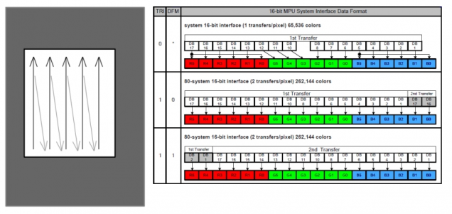
As it turns out, one of the formats supported by the LCD screen is a two-byte (16-bit) colour (5 bits red, 6 bits green, 5 bits blue). This means the palette will only take up 64*2 = 128 bytes. Every little helps!
Next I needed to convert each image into a series of RLE value pairs: instead of listing the colour of every single pixel, we give the device a start point, and end point, and tell it how many pixels – and of which colour – to display.
So a bitmap of, say, rainbow stripes might be described as:
- 20 pixels of colour number one (red)
- 20 pixels of colour number two (orange)
- 20 pixels of colour number three (yellow)
- 20 pixels of colour number four (green)
- 20 pixels of colour number five (blue)
- 20 pixels of colour number six (indigo)
- 20 pixels of colour number seven (violet)
So if we tell the device to start at a specific pixel, and that we’re going to flood fill an area of 20 x 7 pixels, then streamed this data into it, we’d end up with a perfect striped rainbow.
Exactly the same approach is used to draw more complex shapes. Except working out how many pixels and of which colour (and what those colour indices might be) would be a massive job with some graph paper and crayons.
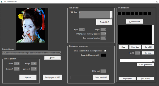
So I made an app into which I could load bitmap data, and it took care of all the tricky number crunching for me
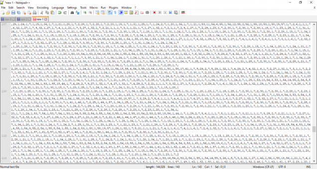
This produced a nice, easy to follow(?!) text file, and I simply entered the numbers exactly as they appeared in the file.
(ok, I didn’t sit and type them all in – I wrote another app for dumping data to the eeprom memory for me)
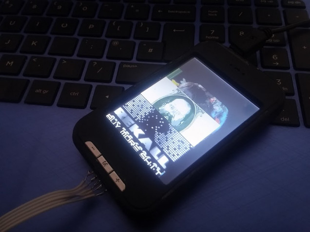
Now it’s just a matter of dragging the data out of eeprom and streaming them to the LCD display. So I did just that. And – amazingly – it worked!
It was really exhilerating to see actual bitmaps finally appear on the screen. Sure, things aren’t quite 100% right; each bitmap just lays over the top of the previous one, and there’s no way of positioning them on the screen yet, but that’s very definitely a series of bitmaps on that LCD!
Success can surely only be hours away……















































Leave a Reply