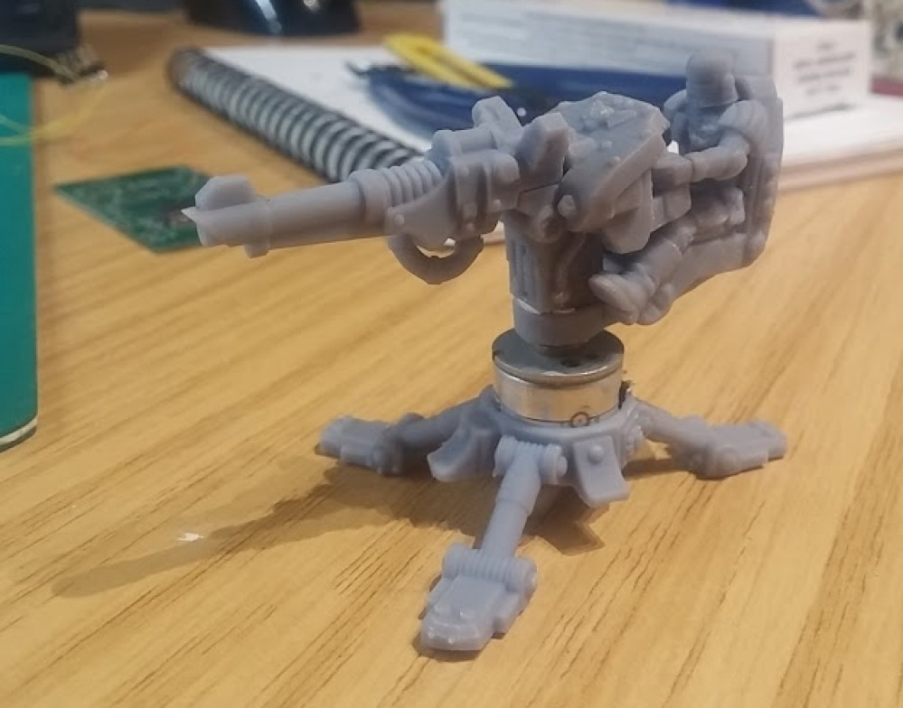
Quick and dirty stepper-motor driver tripod turret
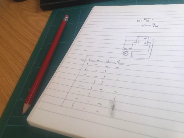
Stepper motor truth table
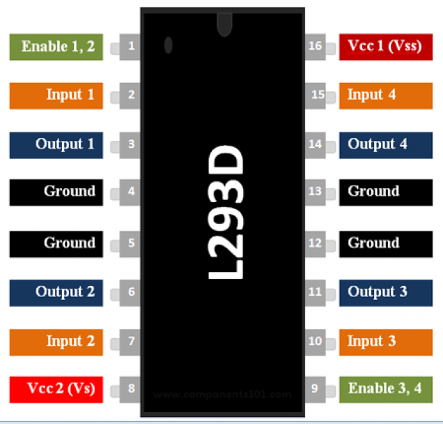
I found an old L239D twin h-bridge chip lying around (from an old CNC project most likely) and had a quick play with it this evening. This chip allows two separate motors to be controlled, and you can change the direction of the current flowing through each, independently – effectively making each one spin clockwise or anti-clockwise as required.
The L239D is often used as a stepper motor driver: if we consider our stepper as two independent motors (since it does actually have two separate coils inside the casing) and by activating the coils in a specific sequence, we can get the motor to turn.
I knocked up a quick “truth table” for the L239D stepper motor. If you imagine the coils to be laid out as in the drawing, the power sequence is as follows:
When current flows through the first coil (at the top) the fixed magnet inside the motor is attracted to the coil (thanks to the magic of electro-magnetism). This is the first “step”.
If we then turn off the first coil and activate the second (at the side) the fixed magnet is attracted towards the second coil – the motor shaft makes a one-quarter turn.
Now let’s activate the first coil again, but this time in reverse polarity. Instead of attracting the fixed magnet, it is repelled, causing the magnet to move as far away as possible from the top coil (another quarter turn). Lastly, we activate the second coil in reverse and this repels the fixed magnet opposite the coil on the right (another quarter turn).
(In truth, a stepper motor doesn’t have a single fixed magnet, it has a number of “teeth” in which magnets of north and south “poles” are arranged so each step is much less than a quarter turn, but the principle remains the same).
So we can make our magnet flick between the 12 o’clock, 3 o’clock, 6 o’clock and 9 o’clock positions. We can also use “micro-stepping” – whereby two coils are activated at once, pulling the magnet to the half-way point between then; this can be used to smooth the rotation, where the steps would otherwise be quite large.
So looking at the truth table, we can see that step one is to activate the top coil by turning on pin 1 of the L239D stepper motor chip – this causes current to flow from pin 1 (on the motor) and pulls pin 2 to ground. In step two, we leave the top coil energised, and turn on the right-hand coil, by setting pin 3 of the L239D chip high (this causes current to flow from pin 3 on the motor to pin 4 which is pulled to ground).
In step three, only the right-hand coil is left energised.
At step four, we activate pin 2 of the L239D chip; this causes current to flow through the top coil again, but this time in the opposite direction as before – from pin 2 (on the motor) to pin 1.
The rest of the steps complete a full rotation of the motor.








![TerrainFest 2024! Build Terrain With OnTableTop & Win A £300 Prize [Extended!]](https://images.beastsofwar.com/2024/10/TerrainFEST-2024-Social-Media-Post-Square-225-127.jpg)





























Leave a Reply