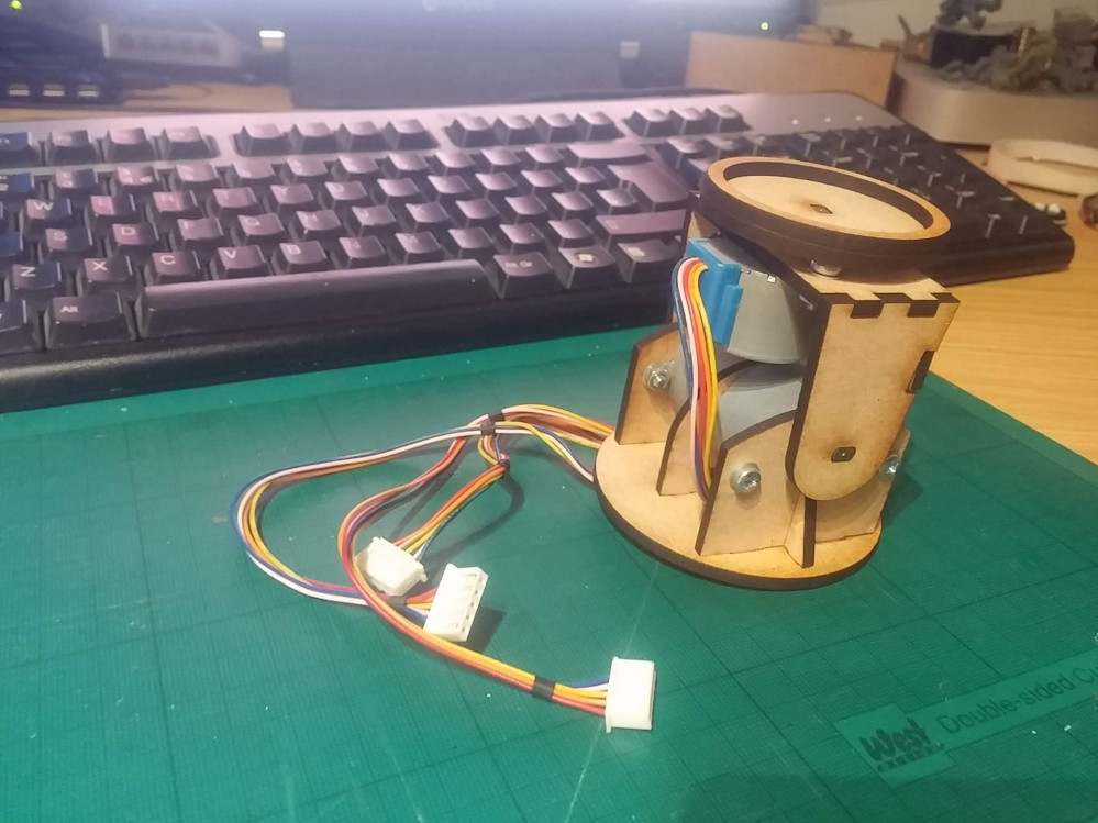
Motorised Painting Handle
Nearly the weekend.....
So, if I get a few hours in the workshop this weekend, I think it’s time to take a proper look at this. First up, it’s got to have that third motor/axis; I thought that maybe two might be sufficient, but I reckon that having an overall “master” rotation is going to be important.
That means I’ll have maxed out all the i/o lines on my microcontroller. Yet I wanted to add even more stuff.
Now, sure, I could add in shift registers and clever trickery like that, to free up some i/o pins on the Arduino, but in all honesty, this project has already taken up more time that I expected it to – and adding in extra complexity like shift registers is just going to chew into the few hours I’ve got available to work on this.
One thing I do think it needs, are sensors to give it a “home” position (from which we can move to any angle/rotation). Since we’re using stepper motors (yes, we… you are building along, aren’t you?) it means that each individual axis can be positioned, accurate to about 1mm (excluding “slop” or “backlash” in the motor gears) by simply counting the steps;
If 4,000 steps are one complete revolution, and we know that the motors will be moving from the same starting position each time, then, in theory, it should be possible to record the position of each motor as it moves – and enable the user to create a number of pre-defined positions to move to.
Now having a list of pre-defined positions and being able to select/enter a name for more (as they are saved to memory) means requiring some kind of screen and a user interface (UI). That’s going to take up more i/o pins, not fewer!
So I figured that we could ditch the joystick and use a smartphone/device for both controlling the motors and as a user interface for the creating/saving settings. That means I can talk to the motors using the (currently unused) serial pins, and connect my “home position” sensors where the joystick used to be.
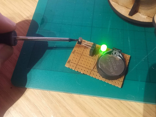
I’ve already used hall effect sensors quite a lot in my interactive playing surface. They’re brilliant little sensors – physically small and can detect the presence of a magnet when placed nearby (the photo above shows how we can use the hall sensor to make an LED light up when a magnet is placed in close proximity).
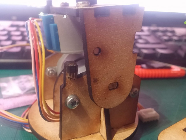
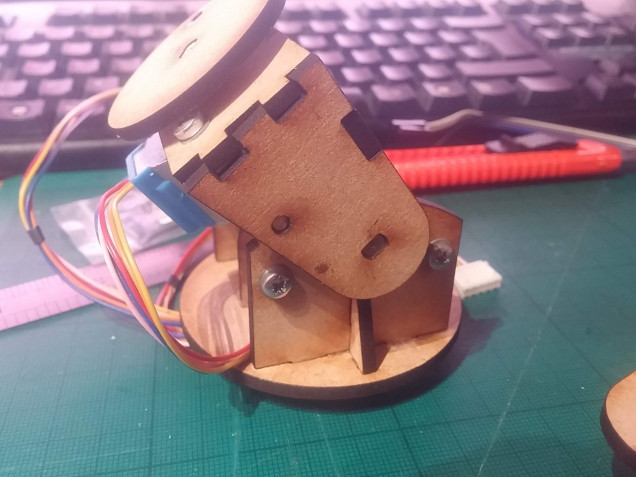
I thought that we could use hall sensors and magnets affixed to the frame of the painting handle to send the microcontroller a message once a specific position has been reached.
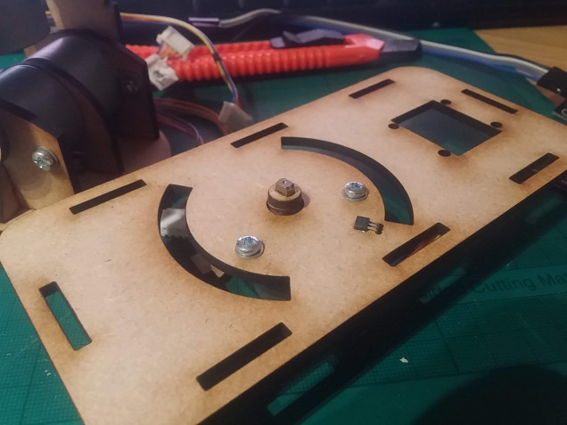
The hall sensor on the vertical part of the frame is triggered when the magnet embedded inside the moving section passes over it. When this happens, we know that the vertical piece is at its furthest extent.
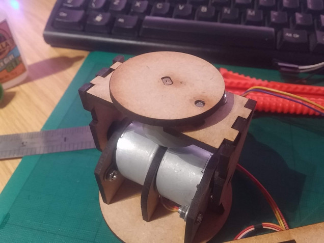
The same applies on the rotating “tabletop” that the miniature stands on – the magnet sits on the rotating part, meaning that we don’t have to worry about wires getting tangled or wrapped around the axle, no matter how many times the top spins around.
The same principle can be applied to the base – although the movement of the entire structure is restricted to just 90 degrees on the base, we can use a hall sensor in the bottom and a magnet embedded into the rotating part, to work out just where in 3D space the thing actually sits!



































Leave a Reply