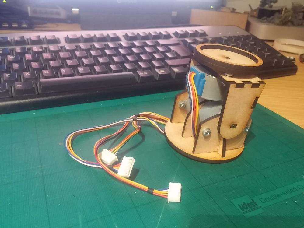
Motorised Painting Handle
Motorised painting handle - first test
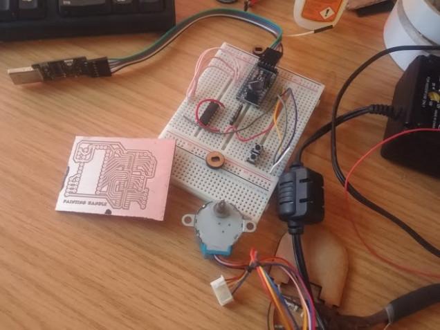
One of the great things of having access to a laser cutter and few litres of ferric chloride is that it’s pretty easy to design, etch and manufacture your own PCBs in about an hour or so.
Here’s the current design, hooked up to the motors via a plug-in breadboard prototyping system. In the final design, things will be much neater and all the nasty wires hidden away, but for developing and debugging, being able to easily unplug pins to work out what’s going on is invaluable!
So far, it’s just a two-axis movement. But it should be more than enough for 90% of miniature painting. I might stick a third axis on it (to allow the entire base to rotate) but that would mean introducing tricky stuff like shift-registers as there aren’t enough pins on a regular Arduino Mini to control four stepper motors AND up to six input buttons.
One quick amendment I made after testing was to add a speed controller. Even at 4,000 steps per revolution, with a delay of just 2ms per step, the motors were making one complete revolution every few seconds. This might sound slow, but given the size of the frame the motors sit in, this actually translates as a lot of movement over a very short space of time.
A simple voltage divider on one of the analogue input pins means I can now change the delay between steps from anywhere between 2ms and 50ms – thus speeding up or slowing down the motors significantly.
Now to build a button interface and see how it all works out!




































Leave a Reply