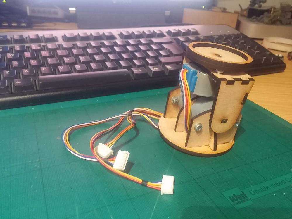
Motorised Painting Handle
....I can't begin to knowing...
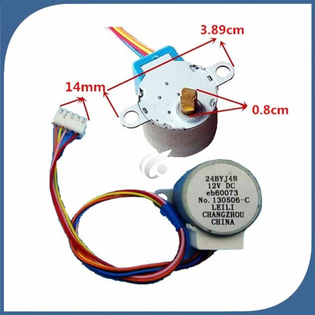
The 28BYJ-48 miniature stepper motor is brilliant for all kinds of homebrew robotics projects. Firstly, they’re cheap. Like a quid-a-shot cheap (if you source directly from China via AliExpress or Taobao). I had loads of these hanging around. Secondly, they’re (relatively) easy to interface with.
I find sticking a ULN2003 (or a ULN2803A) array onto the pins the easiest way to get these motors spining, controlling them via a microcontroller (either Microchip’s PIC or AVR’s Arduino).
The other nice thing about these little stepper motors is that they are quite powerful. As in, for a small form-factor, and for a low voltage, they’re quite torque-y (yep, that’s a word, don’t bother checking). Inside the casing is not just a tiny motor, but also loads and loads of gears.
In fact, these motors are geared down to about 1:4000 or something crazy like that. In short, it means that they’re also quite slow. For home robotics, this might be a problem. For us, it’s exactly what we want!
Stepper motors aren’t quite as straight-forward as regular motors; you don’t just put power to them and watch them spin. They have a number of coils which need to be activated in a particular sequence. The order in which you activate the coils determines the direction that the motor turns.
The benefit over “regular” dc motors is that you can stop the stepper motor dead, after a specfic number of steps have been counted – this makes them perfect for exact/precision positioning. In fact, we’re using the motor more like a regular motor (it’ll either be on or off, in either a clockwise or anti-clockwise direction) but taking advantage of the gearing to give us strength we wouldn’t otherwise have (and did I mention, they’re cheap too!)
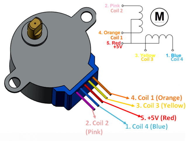
To make this motor turn clockwise, we need to provide it with 5v, and ground certain pins in sequence:
If, for example, we pull the orange and yellow connections to ground, this creates an electromagnetic field in both coils, pulling the centre of the motor into the “bottom-left” position (SW point in the diagram above).
Now, this is where we control the direction.
If we then pull the yellow and pink pins to ground, the centre of the motor is drawn towards the top-left/NW point in the diagram. From here, pulling pink and blue to ground creates a magnetic field which attracts the centre of the motor to the top-right/NE point, and finally, pulling blue and orange to ground attracts the centre of the motor to the bottom-right/SE point.
Start again from the first state, pulling orange and yellow to ground and the motor has completed one full revolution.
Obviously, to get the motor to turn in the opposite direction, you activate the pins in the opposite sequence (orange and yellow, blue and orange, pink and blue, pink and yellow).
(Note for all your techy-nerds: yes, we could also activate each coil individually, creating a micro/half-stepping sequence, but by activating two coils at each time, we keep torque to a maximum).



























Leave a Reply