Digital dice roller
Refining the design
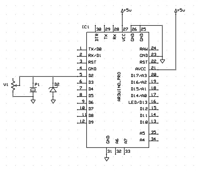
Now, we’ve got a fully protected, give-it-a-whack-to-create-a-digital-signal system here. And if we feed this voltage signal into a microcontroller, we can use it as a trigger (in this case, to say “hey, generate another dice roll, will you?”)
But there’s just one other thing to consider – remember that graph showing the output of a piezo when you give it a wallop?
We’ve filtered out the negative voltages. And we’ve clipped the input voltage so it can’t exceed 5V. But there are still lots of signals, each getting smaller as the signal decays, all in very close proximity to each other.
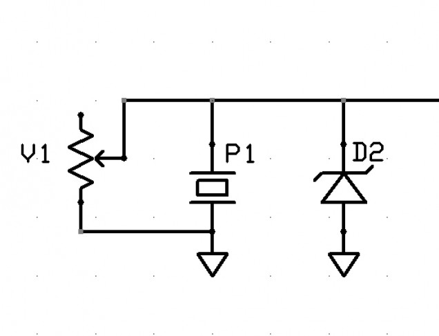
We can get rid of these by introducing a “sensitivity filter” – simply put, we can connect the lead with the generated voltage in it back to ground, through a resistor.
The smaller the resistor, the more easily current can flow through it – so a small resistor means that you need to give the piezo a real whack for any of the voltage to reach our microcontroller input (since the generated voltage would much prefer to go to ground that through a whole series of transistors and complicated logic gates that makes up a microcontroller).
A large value resistor makes current flowing through it difficult, so some of the signal will go to the microcontroller and some of it will pass through the resistor to ground. The larger the value, the more of the signal reaches the microcontroller. The smaller the value, the more of the signal just gets dumped to ground.
In practice a resistor of about 300K (300,000 ohms) is a nice “filter”. It means that a large part of the first, largest “wave” from the generated voltage reaches the microcontroller input pin. But the smaller “ripple” waves pass more easily through the resistor and dissipate to ground.
A resistor of 100K would still work (but it means you have to give the piezo a real clatter for any of the generated voltage to reach the input pin). It effectively “deadens” the piezo as a voltage generator. A resistor of 1M (1,000,000 ohms) means that most of the signal reaches the microcontroller, so the piezo is very sensistive (and creates a lot of signal voltage, even from a very small tap).
Now we could just choose a resistor value, through trial and error, and hope that everyone taps the piezo with a similar amount of force to activate it. And this would be a perfectly acceptable way to proceed.
But to just refine our design that little bit further, we can replace the fixed value resistor with a variable resistor or potentiometer.
This provides a means of changing the amount of resistance cross two terminals, allowing the end user to set their own preferred degree of “sensitivity”. Giving us our final piezo-input circuit:


Leave a Reply