Titan Forge Cyberpunk March Diorama
Things are about to get messy...
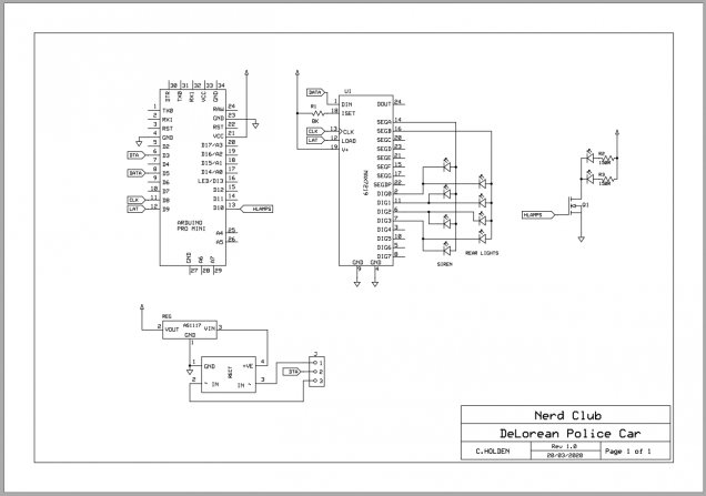
Before creating *any* PCB layout, I like to create a schematic. Although it’s often possible to just squash a few components to gether in layout software and knock up a PCB without one, I find it just helps to organise my thoughts and makes debugging and fault-finding much easier (because, trust me, there’ll be faults to find!)
The circuit for my DeLorean police car consists of a microcontroller, a MAX7219 LED driver, a single 2N222A transistor and a bunch of LEDs.
The Max7219 ensures that the LEDs it controls all have the same, uniform brightness. The transistor allows me to connect the headlights directly to the power rail, so that they can shine just a little bit brighter.
See, the Max7219 works by lighting up a single “row” of up to eight LEDs at a time; it does this really, really fast, so there’s no visible flicker. But it *does* mean that every LED spends a proportion of it’s time turned off.
At 800Hz you don’t get flicker, but it does make the LED visibly less bright than if they were connected directly to the power rail. It’s a compromise I can live with for the rear brake lights, indicator lights and police siren. But for the headlights, I wanted them as bright as possible, so connected them separately.
With only a week til deadline day, I figured I’d only got time to make use of the components I had lying around – pre-populated Arduino Pro Mini boards and the larger-format DIP packaged MAX7219 chips. In an ideal world, I’d use a single TQFP AVR Atmega328 chip, a wide SOIC packaged Max7219 and surface mount transistor(s).
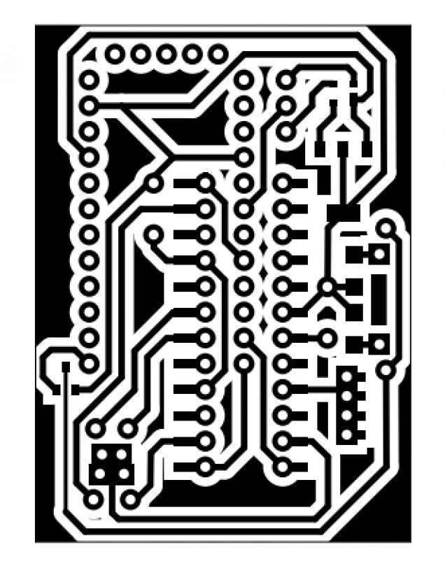
As it is, I’m having to use physically larger components. And no matter how hard I tried, no matter how close I squashed the bits together on the PCB, on a single-sided board (without sending the designs away to be turned into a double-sided, factory made circuit board) I couldn’t make it small enough to fit inside the cavity I’d created in the car body.
Which meant only one thing.
It’s the one sentence every electrical engineer shudders at:
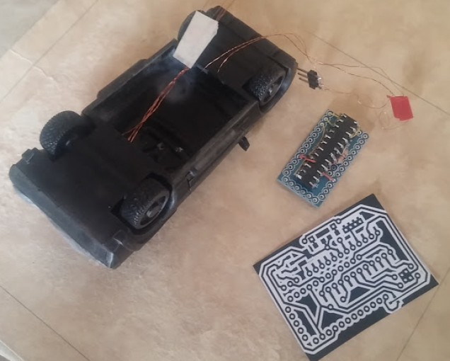
“There isn’t time to do this properly….. we’ll have to dead bug it”
Dead-bugging is the process of wiring components together using wires to connect each of the pins. It’s relatively quick (compared to printing, etching, drilling and populating a PCB) but it’s an absolute nightmare if anything goes wrong, or needs amending in the future.
But time is tight. There isn’t time to do this properly.
So it’s time to get messy…..

















Leave a Reply