Smart controlled daisy-chain RGB LEDs
Arduino neopixels
Arduinos are great little microcontrollers with a huge community to support people getting into hobby electronics. This abundence of people prepared to “have a go” is both the greatest strength of the community, but also one of it’s weaknesses.
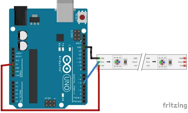
Here’s an example of how to make a string of LEDs light up, using an Arduino. Simply follow the diagram, copy and paste some code and off you go – working multicoloured LEDs!
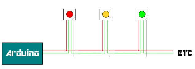
The problem comes when you “outgrow” the examples; many people never need or want to light up more than a dozen or so LEDs – few progress much beyond the example code provided. So what happens when you attach, say, 30 LEDs, and each is connected via really tiny, super-fine, thin wires, rather than joined together in a convenient roll, straight from an eBay electronics store?
Long, tiny, thin wires effectively act like resistors in our circuit. They allow current to flow, but over any kind of distance (even relatively small distances, if the wire is thin enough) we encounter a phenomenon called “voltage drop”.
If you’re into things like that, you can measure the resistance of the wire and use Ohm’s Law and all that to work out precisely how much voltage you’re losing. For the rest of us muggles, we can just think of it like a leaky pipe. A few short runs of leaky pipe, and everything is ok. But if we have a great length, by the time we get to the end of the pipe, little more than a dribble falls out of the end!
Our LEDs require a good, stable 3.5V minimum to work consistently (5V is preferred). Less than this and they behave erratically (and you lose the ability to set each one individually). So we’re going to use a “voltage regulator” on each individual LED and provide much more than 5V on the supply lines. The idea being that if, say, we use a 9V supply and, over the course of 30 individual LEDs, the voltage drop in the wires means only 7V is getting to the last module in the chain, we’ll still have enough supply voltage to “step down” to 5V.
By putting a regulator on every module also means that LEDs closer to the voltage supply don’t appear brighter than those further down the line (as some LEDs will be being fed with a higher voltage).
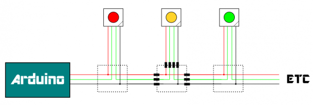
So we need to create two PCBs per LED.
One for the LED to sit on, with the voltage regulator to drop the incoming voltage (anywhere from 9v to 7v depending on its distance from the power source) and another to connect the individual LED to the “ring main”.
The actual PCB designs are pretty simple.
I didn’t even bother building a prototype – I knocked up a few drawings and sent off for ten of each PCB to be made as cheaply as possible; it will probably take a couple of weeks for them to arrive, so I’ll update the project as and when progress is made……..


Leave a Reply