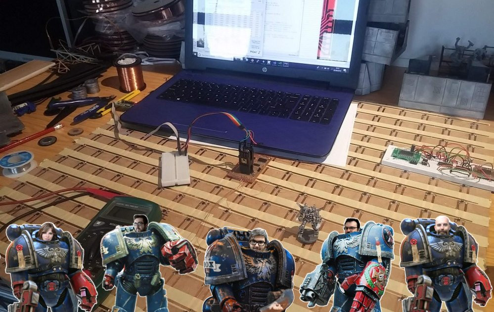
Interactive tabletop playing surface (Space Hulk Hobby Challenge)
How the sensor array works
As development continues, there’s not really much to show on that front, other than a screenful of Visual Studio compiler errors, crash reports and a big pile of hair on my desk, where I’ve been pulling it out for four days.
But there’s more to this project than just coding (would that it were).
I’m hoping to get a video showing the hardware in action in the coming days, but in the meantime there’s been a few queries about what exactly “the hardware” does. It’s basically a grid of hall sensors and as each one is triggered (either activated or deactivated) it sends a message to the game/app via bluetooth.
Here’s a simple demonstration of how hall sensors work; different sensors work on different gauss strengths (i.e. some are more sensitive than others).
Each sensor is connected to a power source (in this case, a simple 3v battery) and ground. As the magnet comes close to the hall sensor, the third leg also gets pulled to ground; if the video I’m using this to make the LED light up. In practice, this leg is connected to an input pin on a microcontroller to create a digital signal (so we can tell when the magnet has been either put close to the sensor – LED would light up – or when it’s been moved away – the previously lit LED goes out).
Now that’s fine for one single sensor.
We’ve got a grid of 256 of them! (that’s a 16×16 arrangement). Even the largest microcontrollers don’t have 256 inputs (and those that do don’t have the necessary pull-up input resistors built in). We need to use a different technique to read the array.
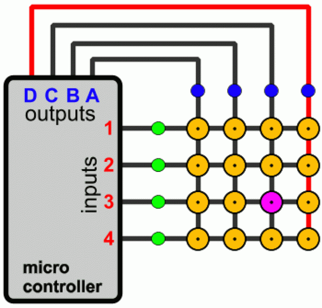
Multi-plexing is the process of reading a grid of sensors (or activating a grid of LEDs if you’re using the output of a microcontroller) in a line-by-line fashion.
The power for all of the sensors are connected in columns. All the inputs from a single row of sensors are connected together. When we get a signal from, for example, input row three, we then look at which column we’ve activated.
By comparing the currently active column and seeing which input row has created a signal, we can work out which individual sensor triggered the signal. By splitting the matrix down into 16 rows and 16 columns, we’ve reduced the number of required microcontroller pins down to just 32.
Luckily, microcontrollers work really, really, quickly.
So we can “scan” through all 16 rows tens – if not hundreds – of times a second; certainly fast enough to provide a timely response when the player places or removes a magnet immediately over a sensor.
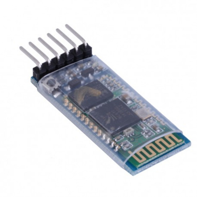
Now all that remains is to create a message to tell our app which particular sensor has detected the change in presence of a playing piece. The easiest way to do this is using a serial-to-bluetooth module. These are readily available, easy to work with and relatively cheap (maybe £3 from eBay).
Simply connect one to the RX/TX lines of the microcontroller and now, when we send data over serial/UART (a relatively simple task for anyone with basic electronics/Arduino/microcontroller experience) the message appears in the app, thanks to the Unity-bluetooth code library.
A bit of hocus-pocus and some code bashing and we can control the characters in our app/game by moving playing pieces over the top of the sensor array. Just a little more debugging and a video will follow very soon……

























Leave a Reply